 Home Page |
TURNERTOYS FLIGHT CENTRAL
IMS Parlor Copter: Supplementary building instructions - 1Updated 3/2/2011Copyright 2010 Ed Loewenton - All Rights Reserved This is a big page - please be patient while it loads Supplement Page 2 Supplement Page 3 DRAGONFLY Performance Helicopter Kit |

|
|
| [User Instruction Pages - Samples] | |||
|
|
|||
BUY A PARLOR COPTER or OTHER MODEL AIRCRAFT SUPPLIES at http://turnertoys.com/competition_kits/helicopter_kit_parlor_copter_w_hanger/
Page 2 supersedes Page 1 in the event of a
contradiction.
|
|||
|
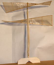
This is the Parlor Copter we built straight from the box,
according to package directions. We subesequently rebuilt it seven or
eight times. See the latest versions and more ideas on page 2. Breakage is most likely to occur during building and handling. We broke a rotor spar by brushing gently (it seemed) against the rotor. The major problem with the kit built as shown here: a pendulum-like oscillation that starts some time after the copter is released and reaches the ceilng. The vane is intended as a damper for oscillation, but is not effective by itself. The major fixes are lowering the lower rotor, and adding a tailboom (keep reading). Balsa stick extending from rotor axis at top of copter helps prevent rotor contact with ceiling or other obstructions. Flies much better with fixed rotor near bottom of motor stick. |
||
|
BENDING WIRE TO MAKE FRONT & REAR NMOTOR HOOKS AND
PROPSHAFT: |
|||
| Basic use of a Rotor Jig | |||
 Pins holding lower spar flat on jig. Optional: Use longer 1/16" spars to make maximum 40cm rotors for maximum lift. Requires modification to jig. |
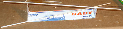 BOTTOM ROTOR: Long spars are positioned first. Lightly glue upper spar to notches in ears of jig. Secure lower one flat on jig with pins. Accurately mark center of spars, center of jig, to position spars correctly, evenly, symmetrical to center hub. Jig ears should be as close to 90° as possible. |
||
| All ribs including center rib should be between spars for smooth joints, not laid on top. See page 2 for alternative method. Placement of rib sticks is somewhat arbitrary. The ribs closest to hub should be about 1.5" from center, the point at which the angle from horizontal should be less than 45 degrees. |
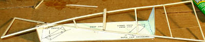 TOP ROTOR: Add ribs, working from hub stick outward. Mark attachment positions with marker for even, accurate spacing. Let glue dry in between pairs of ribs, so handling does not loosen already installed ribs. A drop of Ambroid at inside of joints serves as reinforcing gusset. |
||
|
Mark rib positions on spars before placing spars in jig.
This is much easier, and ensures symmetrical rotors for better
performance. Also mark in red marker the top of the rotor, to remind you which way it should face when assembling it to motor stick. Top of rotor in jig should be facing up in flight. Note that upper rotor rotates counter-clockwise, looking from nose to tail. Lower rotor rotates clockwise, and both should push air downward. Think of a fan blade, or go look at one. Do not apply tissue between hub and first rib. Apply acetone carefully with Q-tip to notches in jig to release spars after assembly. |
|||
|
Assembling 3-pc balsa prop hub and rear vane hub: Old-time standard procedure calls for cutting a groove in on stick, gluing up 2 or 3 pcs to make a channel formed around a piece of wire. One slip and you split the stick. |
|||
|
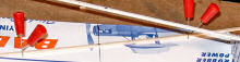
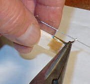
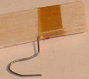
There is a much better way to do this, that is easier
and more forgiving: Mark 2 adjacent sides of a 1/16" balsa stick with marker. Sand the corner between the 2 sides to create an even bevel (white stripe in photo above). Bevel should be just deep enough so that when 2 sticks are cut and mated with the bevels between them, they form v-groove deep enough for music wire when 3rd balsa piece (3rd stick or sheet-balsa vane) is glued on to close it up. |
||
|
For the vane, you must take precautions, as above, to be sure
vane spins freely against pin. For the prop shaft, which is not supposed to move against the wooden hub: Form motor hook and insert wire into hanger, adding washers at front end. Form right angle bend at tip to catch on hub after installation. Leave a sufficient length of straight wire between front bend and hanger so there is at least 1/8" of play; i.e., straight section must be longer than hub stick. Make up ceiling guard (2" to 4") from 2 pieces of 1/16" balsa, by creating V-channel as shown above. Apply glue to the groove and lay straight section of wire into it. Do not get any glue on section of wire passing through bearings or hanger. Then place rotor hub stick over groove to close the assembly, so that front bend in wire shaft bears agains ceiling guard. MAKE SURE ROTOR IS CORRECT SIDE UP BEFORE YOU GLUE IT IN PLACE!! Hold in place with fingers until glue sets up. If you are clever, you can also pin it in place by making a jig of a small corrugated box. TEST THIS ASSEMBLY DRY BEFORE GLUING. Once you apply glue, it is too late to be considering whether it will work or not. Hub stick must be precisely in line with ceiling guard, so that rotor hub will be on axis with motor stick and motor, and rotor is perpendicular to motor axis. When installing top (spinning) rotor, make sure it is facing the right way! It will spin counter-clockwise if you are looking from the nose to the tail, and it should push air in that direction. Always test-fit dry - i.e., without glue. |
|||
|
|
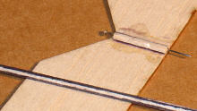
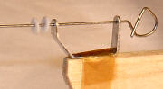
Harlan hanger may need slight adjustment so that wire propshaft is exactly parallel to motor stick. Gently bend section of shaft next to tip, as shown. Avoid twisting hanger and bending it out of plane. You should not need to adjust so much that tip section of shape moves measurably off 90° from motor stick. If that happens, you have done something wrong!! | |
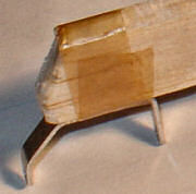
| At left: Harlan Prop Hanger, installed with approx. 1 1/2 wraps of Ambroid saturated tissue. Thin glue with acetone. Note balsa is cut back to ensure rotor clearance. For greater strength, where tissue wrap around glue joints is required, use up to 2 layers saturated with Ambroid cement. Squeegee off excess glue with balsa stick, moving in same direction as wrap so as to tighten tissue. Do this for prop hanger and rear motor hook. | |||
 Use 2 pairs small round-nose pliers in good condition to form wire. Be careful to keep all bends in same plane. |
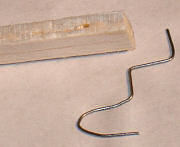
 This tailhook was made with extra length on section vertical to motor stick to provide additional motor clearance from stick. This is not necessary with Dragonfly model. |
 Propshaft and rotor are installed before hook is formed at forward end of propshaft so that it catches ceiling guard and/or end of rotor hub. 2 Teflon washers are shown on wire. |
|
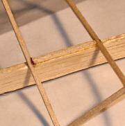 Gluing fixed (lower) rotor to motorstick: Apply glue to rotor hub and motor stick, hold in accurate alignment with motor stick until glue sets. Make sure it is facing the right way so it pushes air backward. It will rotate clockwise looking from front to back - opposite of top rotor. |
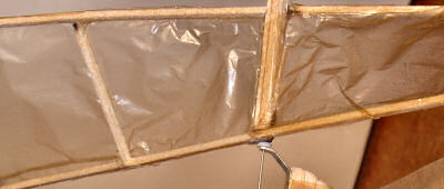 Tissue covering, right & wrong: We applied tissue covering to opposite sides of rotor frame on either end so it is facing the direction of thrust, where air pressure is higher. This was wrong. It should be on side of rotor facing up, i.e., in the direction of travel. The image shows tissue applied all the way to hub. This is wrong. Leave the section nearest hub open. |
||
|
Mylar is supplied with Dragonfly kit for rotor covering. See Page
4 for application. Supplement Page 2 Supplement Page 3 Dragonfly Directions (Page 4) DRAGONFLY Helicopter Kit order page |
|||
|
|
|||