 Home Page |
TURNERTOYS FLIGHT CENTRAL
The DRAGONFLY™: Construction Protocols
Copyright 2010-2011 Ed Loewenton
- All Rights Reserved |

|
|
| [User Instruction Pages - Samples] | |||
|
|
|||
The DRAGONFLY is a full-size, SO-legal, high performance Balsa Helicopter.
It is a design lab for experienced builders who have built and flown a basic IMS Parlor Copter
kit or similar design with fixed and free-rotating rotors, and understand the
basic concepts and procedures.
Buy a DRAGONFLY
|
||
|
We built The DRAGONFLY from scratch, sticking to the basic design concepts
of the modified Parlor Copter (Page 1,
Page 2).
It has a design weight of about 3.95g. A beat-up model at 4.18g flew about
1:45-1:50. DRAGONFLY design includes: * free rotating top rotor on rubber motor with ceiling guard. * fixed lower rotor, attached to motor stick, as low on stick as possible. * 3/32" (optional 1/8") motor. * Tailboom with free-rotating vane * Full 40 cm rotors with cambered ribs * Shorter motor stick with tapered aft end (to save weight) * lower rotor below rear motor hook (avoids interference with motor; allows blocking it up so it is in line with motor & upper rotor axis; allows placement a great distance from upper rotor). * A universal rotor jig that will assemble both upper and lower rotors Basic building guidelines: * Weight counts! You are lifting a dead weight with no glide. Extra weight steals energy. Less weight means more time in the air. * You need as much motor torque as you can get. A 2.0g motor that is long and thin has as much total energy as a short thick one and can take more winds, but delivers less torque for a longer time period. It may never produce enough torque to actually lift the copter. Modifying rotor size and pitch for faster RPM might address this, but it gets complicated. Most successful copters use heavy motors with lots of initial torque. BUILDING THE DRAGONFLY - a Helicopter with 40cm rotors, cambered ribs, tailboom. (see also Pages 1 & 2). All dimensions are nominal, except for the maximum legal rotor diameter of 40cm. Supplied motor stick is approximately 12", may be tapered, sanded, cut to reduce length. Model on this page has 11.5" motor stick. REMEMBER AT ALL TIMES THAT BALSA IS EXTREMELY FRAGILE!! Avoid quick movements when anywhere near your model. It is best not to wear loose-fitting clothing, which may brush against model; rolled-up sleeves are safer. Build a universal jig that will do both rotors. 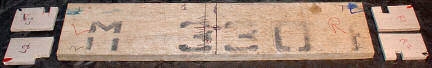 Base is 3/8" utility grade balsa. 2 ears are cut from 1/8 or 3/16", with accurately square corners. Our sheet was not as wide as base, so we split it. Edges of ears must be flush with edges of base, bottoms aligned with bottom of base. Note cutouts in ears so lower spar can sit on corners of base.(see image below.) Use a tri-square to mark the center lines on base. How wide is base? How tall are ears? This is arbitrary - determines chord and pitch, neither of which are specified by rules. |
||
|
Base as shown (& in kit) is 14.25" L x 3.25" W x 1
7/16" thick. Ears
are 2" tall; top of ears is 1 9/16" above base. Note cutouts so
lower spar can be placed at corners of base. Ear corners are notched 1/16 x 1/16, marked red and black to identify positions for upper vs lower rotors. |
|
|
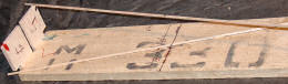
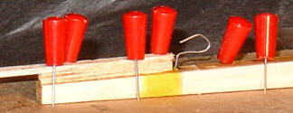
Assemble the rotors: 40 cm (maximum spar) = 15.88". We used 15.75" spars. The idea is always to be a fraction of a percent on the safe side of the rules. Rib positions are marked on the spars before attaching spars to jig. The lower spar is held with pins, centered and positioned over the corners. The upper spar is lightly glued to 1/16" notches in ears. Use Ambroid so temporary joint can be loosened. 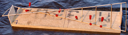 The top rotor is shown here: it will rotate counter-clockwise. Lower rotor uses ears that are reversed, that is, the spars go diagonally the other way, so notches for upper spar are on the other side of ears. Secure lower spar with pins, aligning center mark accurately with center mark on jig base. Use a square-cornered balsa or cardboard piece to align center mark on upper spar with center mark on board and lower spar. Hub is installed first. Hub is straight 1/16" stick. Upper spar will sag, so lift gently until it is straight, hold hub stick in place, and mark distance between spars. Cut a little oversize, test fit dry, and trim until it just fits when spar is straight. Glue in place and let set up firm before moving to first cambered ribs from center. Measure, cut, and gradually trim each pair of ribs in this way, until they fit between ribs at or near your marking with a very slight tension against spar (a firm but delicate fit). Let each pair set up firm before moving outward to next pair. Cambered ribs are installed with convex side up. Mark each rotor so you remember which is upper/counterclockwise-rotating and which is lower/clockwise-rotating, and which side faces up.. |
||
|
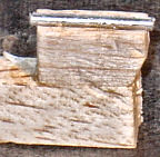
A block of appropriate thickness is glued to rear of
motor stick. Glue up scrap pieces from the 1/16" vane sheet to build
block to desired height. Tailboom is glued to block. Hub of lower rotor will be glued on top of tailboom. The idea is to get rotor hub and tailboom on axis with motor and upper rotor. End of motor stick is tapered starting just aft of motor hook to save weight. |
Tail of motor stick could be shaved a lot thinner than shown here, or cut step-wise. Strength is not a concern here. |
|
|
Top rotor is attached to motor shaft by gluing up 2 1/16"sticks with groove between them to hold wire (This is the ceiling guard - see Pp. 1 & 2 for hub assembly details.) Wire is completely formed and inserted into hanger with teflon bearings, then front bend is made to bear against ceiling guard. Then exposed wire is laid into groove and rotor hub is glued on top to capture wire. It is OK to get glue in groove, but NOT on spinning metal-to-metal parts or bearings. If necessary, clean bearings and rotating shaft section with WD-40, then acetone applied with Xacto knife. Hub must be virtually friction-free, so it moves just by exposure to room air currents or light breathing. |
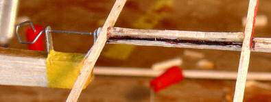 Complete top rotor assembly was attached to hanger as shown. Assembly and stick were (patiently) held together by hand until glue set up - about 5 minutes. Then hanger was glued to motor stick -again, clamped by hand and held for 5 minutes. Be sure all parts are accurately centered and aligned! |
|
|
Alternate Motorshaft Bearing/Prop Hanger Design This structure may provide a means of attaching rotor that is more stable under full winding torque. Use small tube and 1/8 x 3/8 balsa supplied in parts bag. Cut a balsa piece slightly small than tube length. Block height is adjustable by cutting block (make dure to maintain squareness!). Assure alignment by marking centerline with 2 parallel lines drawn with carpenter's tri-square. Glue tube to block and block as shown to front end of motorstick. When thoroughly dry, wrap with tissue soaked in Ambroid thinned with acetone so that tissue is snug. Or wrap tightly with thread and coat with Ambroid/acetone mix. Install rotor with bearings as shown above. Top Of Page |
|
|
APPLYING MYLAR COVERING |
||
|
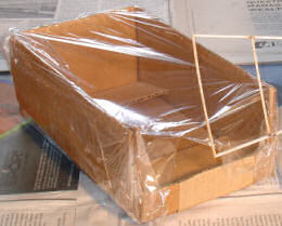
Don't be intimidated. It's not that hard. Use 3M #77
spray adhesive (from hardware store.) Follow can directions. We covered upper
rotor after installing shaft/hanger/ceiling guard, to avoid excessive handling
after Mylar was in place. Lower rotor can be covered before attaching to
motor stick. Use a small corrugated box with length and width about 4" larger than the section of rotor to be covered. You are covering only the outer 3 sections (outer 4 ribs). Fold flaps outward and tape securely into place. Cut away one end. Spray a light dusting on the resulting rounded top edge. This should yield the stickiness of a Post-it Note, which will release the Mylar easily and is resusable for several applications. Roll out a section of Mylar onto the sticky edge, loose enough so it sags a fair amount near cutout end of box. Cut several inches away from box, to avoid propagating a tear into working area. |
|
|
Mask the areas of the model not to be sprayed. Apply
a very light spray to the UPPER surface of the frame, including only
up to the 4th rib. If the ribs are cambered, this is the CONVEX side. Lay the sprayed frame into the mylar stretched on the box/frame, convex side down. Cut it free along outside of frame with a small solder-pencil. Do not use a cutting tool. See directions that come with Turnertoys Mylar. Top Of Page |
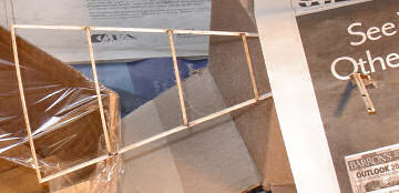
The rotor-hanger assembly has not yet been glued to motor stick at the time of mylar application |
|
|
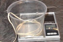
MAKING and USING A 2g MOTOR It's a good idea not to have a motor that is exactly 2.00g. If the judges' scale is not standardized to yours (how could it be?), you risk disqualification. Aim for a few hundredths underweight. |
||
|
Use a small plastic container. The one shown
weighs about 20g. Set tare mode on scale. Feed out rubber until scale reads
about 2.10g and cut string. Sharp scissors work better than a knife. Put your O-ring into container, and trim rubber
in very small increments until total weight is about 2.02g. Make up loop with O-ring, and tighten knot so minimal rubber protrudes past knot. Trim this fairly close. Motor should now weigh about 1.96g. Silslick lube will make up to an additional .02g, for a total of just under 2.0g. Top Of Page |
|
|
1/8" and 3/32" rubber is supplied with the kits - enough to
make about 5 motors of each size. The DRAGONFLY as tested uses an approximately 2.0g/10" double loop (4 strands) of 3/32 rubber. With a double loop, both loops must go through the O-ring. The loops must be perfectly even with one another when hanging loose. Adjust the strands until they are. The O-ring should sit just up against the knot. The knot is placed at the rear end of the motor stick, so it does not rotate and catch the stick. Thorough lubrication is essential with a double loop! 800 winds of 3/32 double loop yields great initial torque, probably near the structural limits of the model. You may also use 1/8" rubber. We applied about 1,000 winds to 1/8" rubber. We make no guarantees about the number of winds you can apply! The number of winds before either the motor or the model breaks depends on lubrication of motor and how well you have constructed your model, among other things. If the motor breaks, there is a risk of damage to the rotors. A poorly installed hanger may be pulled loose, damaging model. . March, 2011: WINDING A HELICOPTER MOTOR FOR COMPETITION FLYING: We suggest you consider switching roles for the person winding (usually the pilot) and the assistant. Since the pilot will have to hold the rotor stationary until launch, it makes more sense to let the person winding be the assistant and let the pilot hold the rotor shaft and front of motor stick. Consider practising all maneuvers without any winding torque in the motor, until all moves are well learned. * An assistant holds the front of the motor stick with the thumb and forefinger, and holds the rotor stationary with the other hand with a gentle, even grip applied with thumb and finger to the motor shaft and rotor hub. Do not apply leverage to the rotor frame itself. Avoid touching rotor except at hub. Loss of grip may destroy your model - practice this grip with a light winding.. NOTE: Should the motor snap back to the assistant's hand, the assistant must insure that the model is not dropped or released. THE ASSISTANT’S JOB IS VERY IMPORTANT IN CONTRIBUTING TO THE SUCCESS OF THE TEAM. * Your copter motor will be wider than for fixed wing craft (typically .125" or heavier), so the motor must be stretched out approximately just two times its normal length and should be at a 10-15 degree angle away from the motor stick. Apply about half the desired number of winds while it is stretched. Then bring crank gradually in toward motor stick so winds are completed with motor at its final length. * Begin turning the crank handle in a clockwise motion to wind the motor. For the first few flights put in approximately 300 total turns into the rubber motor (divide the motor turns by the gear ratio to arrive at the number of crank handle turns). * After the first flight is completed, and adjustments are made, add an additional 100 turns into the motor. Wind half the planned count; then the person winding the motor should slowly walk toward the rear motor hook so that the rear o-ring is at the rear motor hook at the completion of the winding process. * In subsequent flights, use the design or specification count of winds. Wind half count with motor stretched 2x, then walk the winder in during that second half. BOTH THE WINDER AND THE ASSISTANT MUST BE SURE THAT THE O-RING IS SECURELY IN PLACE ON THE REAR HOOK BEFORE RELEASING IT FROM THE WINDER HOOK OR LETTING GO OF THE ROTOR HUB AND SHAFT.. FAILURE TO EXERCISE DUE CARE COULD RESULT IN A DESTROYED MODEL. Top Of Page |
||
|
|
||
|
Just for fun... Balsa Glider & MotorPlane Sampler Ready-to-Fly Balsa Motorplanes Build-&-Fly Balsa Kits
|
||